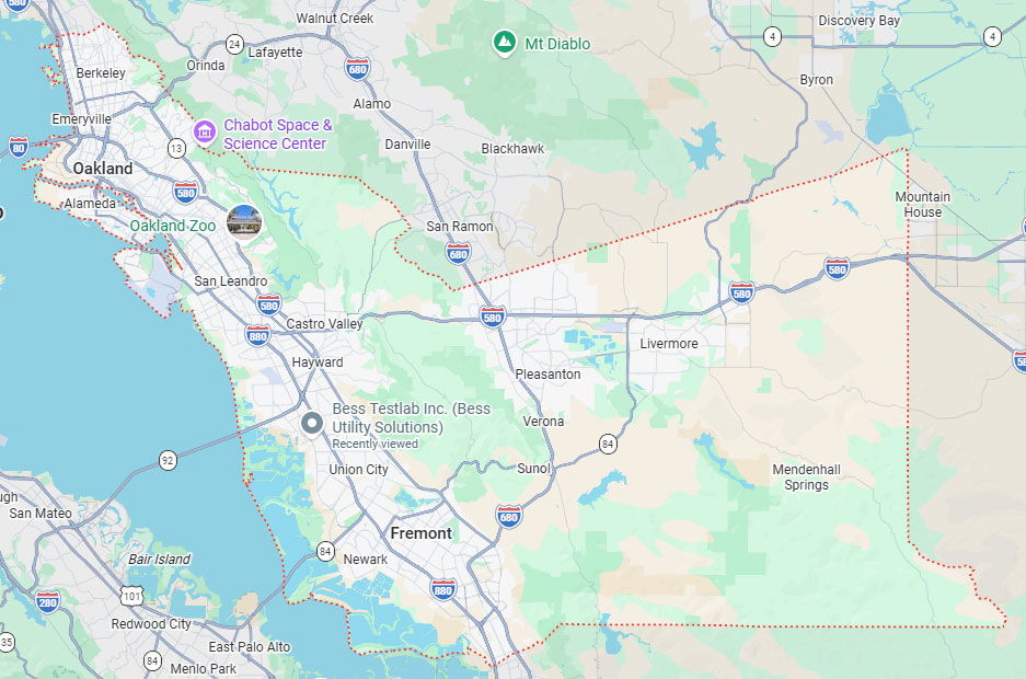
Hayward, CA
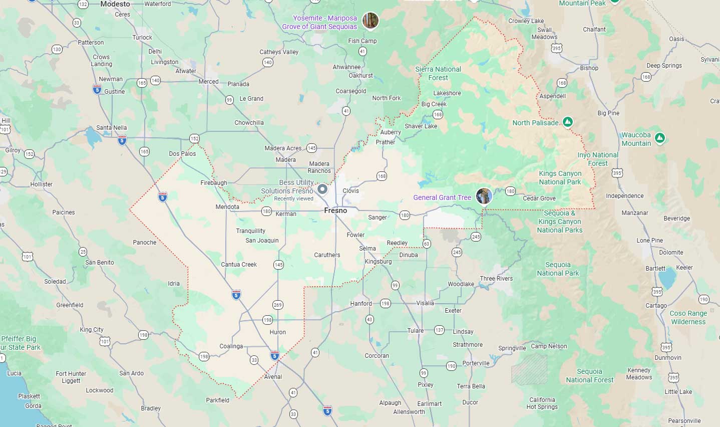
Fresno, CA
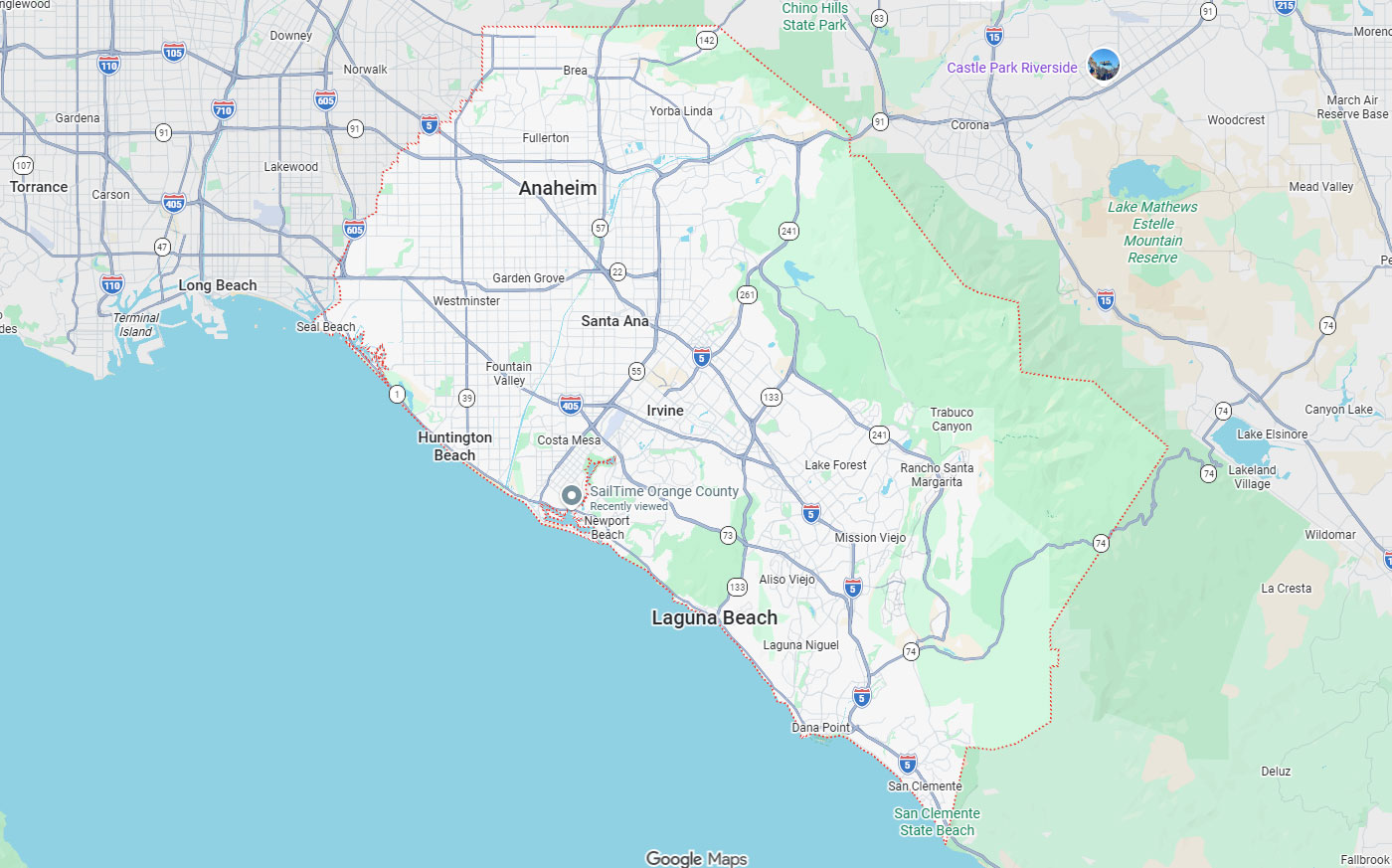
Orange, CA
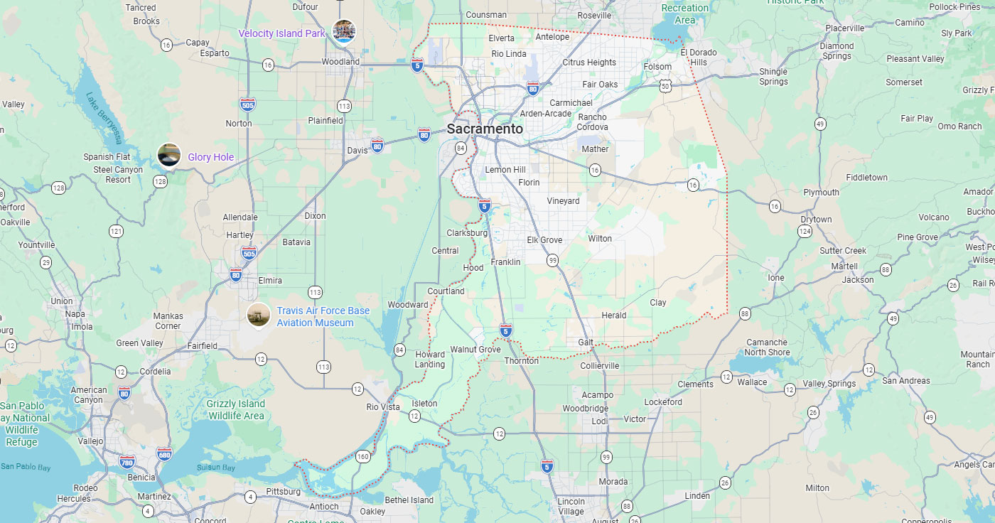
Sacramento, CA
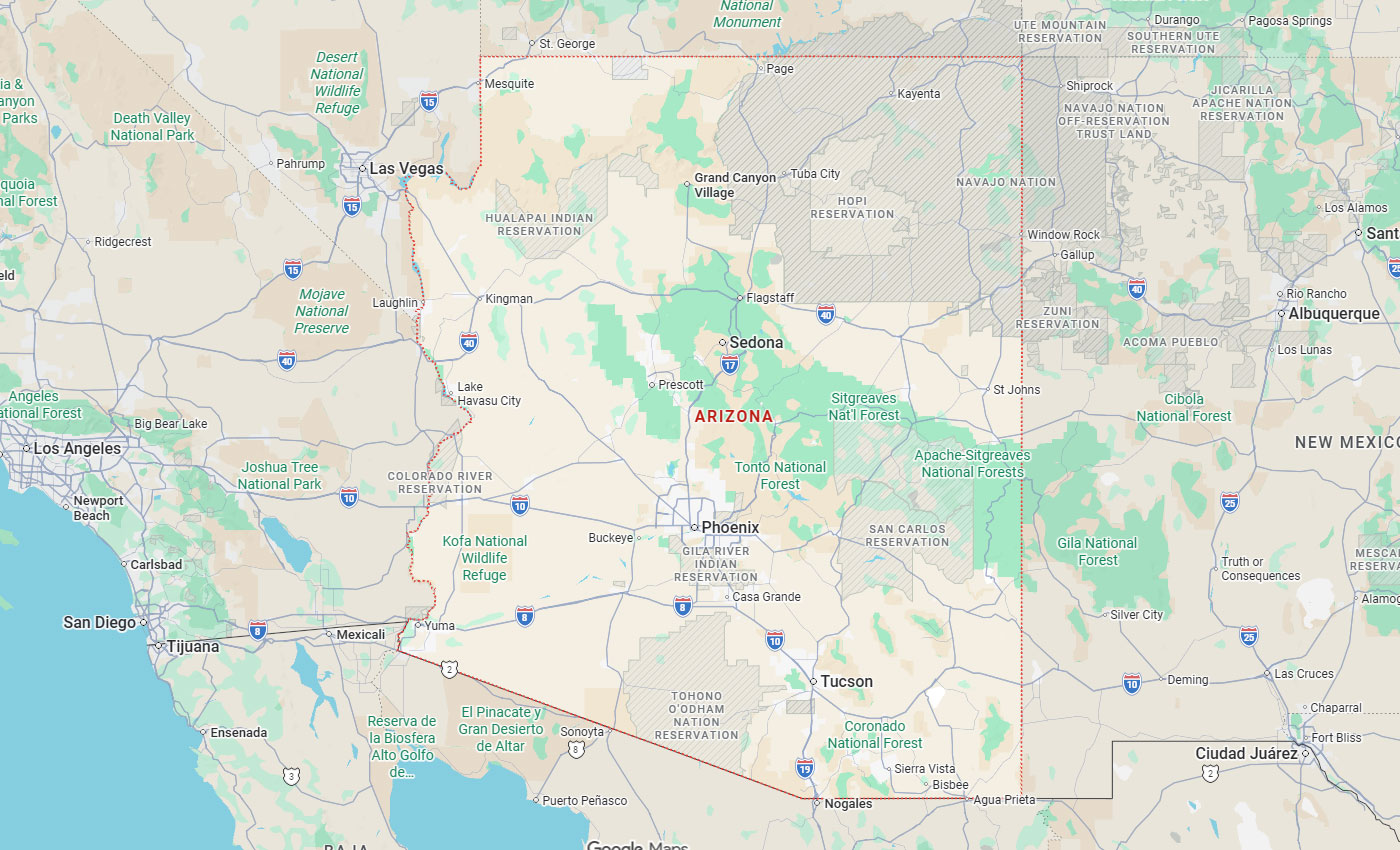
Phoenix, AZ
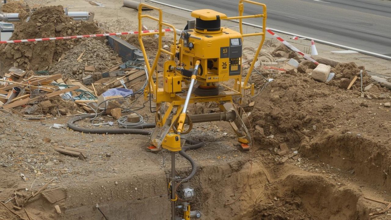
San Francisco projects often involve dense infrastructure, older utilities, occupied buildings, tight schedules, and limited access. Hitting a line or cutting into the wrong slab component can create safety, schedule, and budget issues. GPR scanning for concrete and underground utilities in San Francisco gives crews a read on what sits inside a slab or below grade before the first cut, which is where underground locating and detection work begins.
GPR scanning for utilities helps teams investigate concrete and subsurface conditions before work begins, but accuracy depends on planning, interpretation, and verification. Below, you'll find when ground-penetrating radar SF technology is useful, when to combine it with electromagnetic locating or vacuum excavation, what changes the quality of the data, and how an integrated workflow supports Bay Area project delivery.
Key Takeaways
Ground-penetrating radar sends electromagnetic pulses into concrete or soil and records the reflections. Trained technicians read those patterns to identify rebar, conduit, voids, utilities, and other anomalies.
GPR sends high-frequency radio waves into soil or concrete. Where those waves meet a material with different electrical properties, they reflect back to the antenna.
Time delay and signal strength indicate depth and material type. Reading them takes an understanding of wave behavior, site conditions, and target properties, since soil features and construction debris can look like utilities.
Concrete scanning examines structural slabs, walls, and beams to locate embedded rebar, post-tension cables, conduits, and voids. GPR concrete scanning supports safe coring, cutting, and drilling by identifying features that could compromise structural integrity or create hazards.
Underground utility locating maps buried gas, water, sewer, electrical, telecom, and fiber below grade. Subterranean mapping technology prevents strikes during trenching and tie-in work by showing horizontal position and approximate depth.
Electromagnetic locating traces conductive utilities such as metal pipe and energized cable using induced or passive signals, but it needs contact or signal induction to work.
Vacuum excavation gives positive identification by exposing utilities without damage, so material, size, and depth can be confirmed on site. Records review, survey-grade mapping, and pipeline inspection cameras round out the investigation.
San Francisco construction, renovation, and infrastructure work happens in tight sites with aging utilities and public visibility. Early subsurface investigation cuts the risk of strikes, delays, failed inspections, and emergency repairs.
Older municipal records may be incomplete, hand-drawn, or out of line with current survey control. That uncertainty forces crews to dig cautiously or stop until utilities are confirmed.
Private developments, tenant improvements, and seismic retrofits often run into unmarked or abandoned lines. Dense utility corridors under sidewalks and roadways raise the odds of a conflict during trenching, boring, or tie-in work.
Utility strikes bring injury, repair costs, schedule damage, and public disruption. Cutting rebar, tendons, conduit, or embedded utilities during coring, cutting, or retrofit work creates an immediate hazard.
Hitting a gas line, fiber trunk, or live electrical service can trigger evacuations, outages, and regulatory review. Failed inspections and change orders add cost and schedule damage beyond the repair itself.
Limited access, traffic control, and occupied buildings make exploratory digging expensive and disruptive. Preventing costly utility strikes through early scanning protects schedules and reduces public impact.
Pedestrian zones, transit corridors, and commercial districts need fast mobilization and minimal surface disturbance. Noninvasive concrete underground line detection supports faster permitting and safer work in those settings.
GPR serves a different purpose depending on whether the target sits inside concrete or below grade. Knowing which applies helps teams pick methods and set expectations.
GPR scanning detects rebar, conduit, post-tension cables, voids, and embedded utilities before cutting, coring, drilling, or demolition. Structural renovation, seismic upgrades, and MEP installations all need a clear read on slab makeup first.
Slabs in tenant improvements, elevator and stair openings, and MEP coring are often densely reinforced. Scanning shows the layout and depth, so a drill location can move a few inches instead of cutting a tendon.
GPR detects metallic and non-metallic utilities depending on depth, soil moisture, and line size. Concrete, PVC, and clay pipe reflect when their electrical properties differ from the surrounding soil.
Electromagnetic locating stays useful for conductive utilities that carry or accept a signal, while GPR covers the non-metallic lines it cannot trace.
Tenant improvements, seismic upgrades, MEP retrofits, elevator and stair openings, and coring for plumbing, electrical, and HVAC all call for concrete scanning before any concrete cutting and coring work starts. These projects need certainty about embedded features before crews drill into an occupied structure.
Sidewalk and roadway work, trenching, utility tie-ins, private campus and facility work, municipal improvements, and commercial redevelopment call for underground utility locating. Early mapping lowers excavation risk and supports design coordination for new infrastructure.
| Factor | Concrete Scanning | Underground Utility Locating |
| Where the target sits | Inside slabs, walls, decks, and beams | Below grade in soil, fill, or pavement |
| Common targets | Rebar, post-tension cables, conduit, voids, embedded lines | Gas, water, sewer, electrical, telecom, fiber |
| Typical depth | A few inches to about 18 inches of concrete | Surface to several feet, depending on soil |
| Risk it prevents | Cut rebar or tendons, structural damage, injury while coring | Strikes, outages, evacuations, emergency repairs |
| Usual project types | Tenant improvements, seismic retrofits, MEP coring, stair and elevator openings | Trenching, tie-ins, sidewalk and roadway work, redevelopment |
| Verification step | Test drill or shallow core inside a marked clear zone | Vacuum excavation or potholing to expose the line |
Accuracy tracks target depth, size, and material, soil and concrete conductivity, moisture, access, congestion, records, and technician interpretation. No technology detects everything in every condition, so the variables below set realistic expectations.
| Variable | Effect on results | How to manage it |
| Soil conductivity and moisture | Clay, saltwater intrusion, and saturated fill absorb the signal and cut usable depth | Pair GPR with electromagnetic locating and plan exposure points |
| Target depth and size | Small or deep targets return weak reflections that blend into noise | Adjust antenna frequency and grid spacing, then verify by exposure |
| Material contrast | Non-metallic pipe in similar soil shows less contrast than metal in dry sand | Cross-check records and trace conductive lines with EM locating |
| Rebar density and slab makeup | Tight rebar mats, aggregate, and overlays mask features below the first layer | Scan from two directions and mark clear zones, not single points |
| Surface access | Traffic, occupied floors, and obstructions limit scan coverage | Book access windows and set traffic control up front |
| Records quality | Incomplete or misaligned as-builts leave unmarked and abandoned lines out | Review records first, then treat field data as controlling |
Highly conductive or wet soils reduce GPR penetration and cause signal attenuation that hides deeper targets. Clay-rich soils, saltwater intrusion zones, and saturated fill are harder scan environments.
Concrete makeup, including aggregate size, rebar density, and moisture, changes how the signal travels and reflects. Soil conditions affect GPR accuracy by changing electrical conductivity and wave velocity through subsurface materials.
Small, deep, or low-contrast targets return weaker reflections that are harder to separate from background noise. Shallow, large, or high-contrast features give stronger signals and clearer reads.
Exact depth cannot be guaranteed because wave velocity shifts with material and moisture. Confidence depends on site conditions and may call for potholing or FHWA Quality Level A exposure.
GPR data needs experienced interpretation, since a raw image is not a construction-ready utility map. Technicians classify anomalies by correlating reflections with records, surface features, electromagnetic results, and site knowledge.
A layered workflow of records, electromagnetic locating, GPR, mapping, and exposure builds confidence in stages, and each kind of confidence depends on how far the investigation goes.
GPR is one tool inside subsurface utility engineering, which combines records research, surface geophysics, mapping, and exposure. FHWA describes SUE as civil engineering, surveying, and geophysics working together to cut subsurface uncertainty.
| Quality level | What it delivers | Method | Certainty |
| QL-D | Existence of utilities from records | Records and as-built research | Lowest |
| QL-C | Surveyed surface features tied to records | Survey of visible appurtenances | Low to moderate |
| QL-B | Existence and horizontal position | Surface geophysics: GPR and electromagnetic locating | Moderate to high |
| QL-A | Horizontal and vertical position, material, size, condition | Non-destructive exposure by vacuum excavation or potholing | Highest |
FHWA Quality Level B covers the surface geophysical methods that establish existence and horizontal position, which is where GPR and electromagnetic locating sit alongside records review.
Electromagnetic locating remains useful for conductive utilities that can be traced or energized. A complete utility locating workflow integrates utility maps and records, electromagnetic pipe locators, GPR, utility mapping and CADD conversion, traffic control, and strategic consultation.
FHWA Quality Level A is the highest accuracy level and involves nondestructive exposure of underground utilities. Positive identification through vacuum excavation and potholing provides higher certainty by exposing the utility for visual confirmation.
Potholing confirms material, size, depth, and condition before final design or excavation mobilization, which settles conflicts on paper instead of in the trench.
Detection confidence says whether a target is likely present based on GPR and electromagnetic data. Horizontal location confidence says where it sits relative to surface marks or survey control.
Depth estimation confidence is approximate in many scans and remains condition-dependent without exposure verification. Target classification confidence relies on correlating GPR patterns with records, electromagnetic results, site knowledge, or exposure, and surveying and mapping converts field data into actionable construction documents.
No method finds everything in every condition, so knowing the limits of GPR prevents overreliance. Stating confidence honestly lets teams plan the right verification steps.
Dense rebar, post-tension cables, stacked utilities, and poor surface access all make interpretation harder. Clutter from congested corridors or buried debris produces ambiguous reflections that need a second data source.
Pavement thickness, asphalt layering, and concrete overlays affect penetration depth and target visibility. GPR is critical for utility mapping in complex urban environments, but interpreters must acknowledge uncertainty when conditions degrade data quality.
GPR does not replace 811 notification, engineering review, safe excavation practice, or exposure when stakes are high. Confidence levels describe likelihood rather than certainty, and they move with target and site conditions.
Results track site conditions, target material, depth, access, and operator interpretation. Ask a provider to explain confidence and verification options rather than accept an absolute promise.
811 is essential, but private lines, abandoned lines, non-conductive utilities, embedded slab features, and complex facilities may require private locating, GPR, mapping, and potholing. Underground utility locating services in California complement public notification systems by addressing gaps in coverage and record accuracy.
Coordinate notifications and safe digging procedures, including hand digging near marks and trench shoring. Compliance, worker training, and equipment choices stay with the contractor no matter how good the scan was.
Bess Utility Solutions integrates utility locating, GPR concrete scanning, vacuum excavation, utility mapping, CCTV pipeline inspection, concrete cutting and coring, traffic control, surveying and mapping, leak detection, and existing conditions analysis. One provider across those scopes cuts coordination work and keeps risk management continuous from design through construction.
The same crews handle detection, marking, mapping, and exposure, so field findings turn into construction documents without a handoff between vendors. Combining surface geophysics, electromagnetic detection, and nondestructive exposure gives project teams layered confidence instead of a single data source.
Working with one provider across detect, interpret, mark, map, verify, and excavate removes vendor coordination. Regional presence supports fast mobilization for urgent scanning, emergency locates, or potholing across the Bay Area and Northern California.
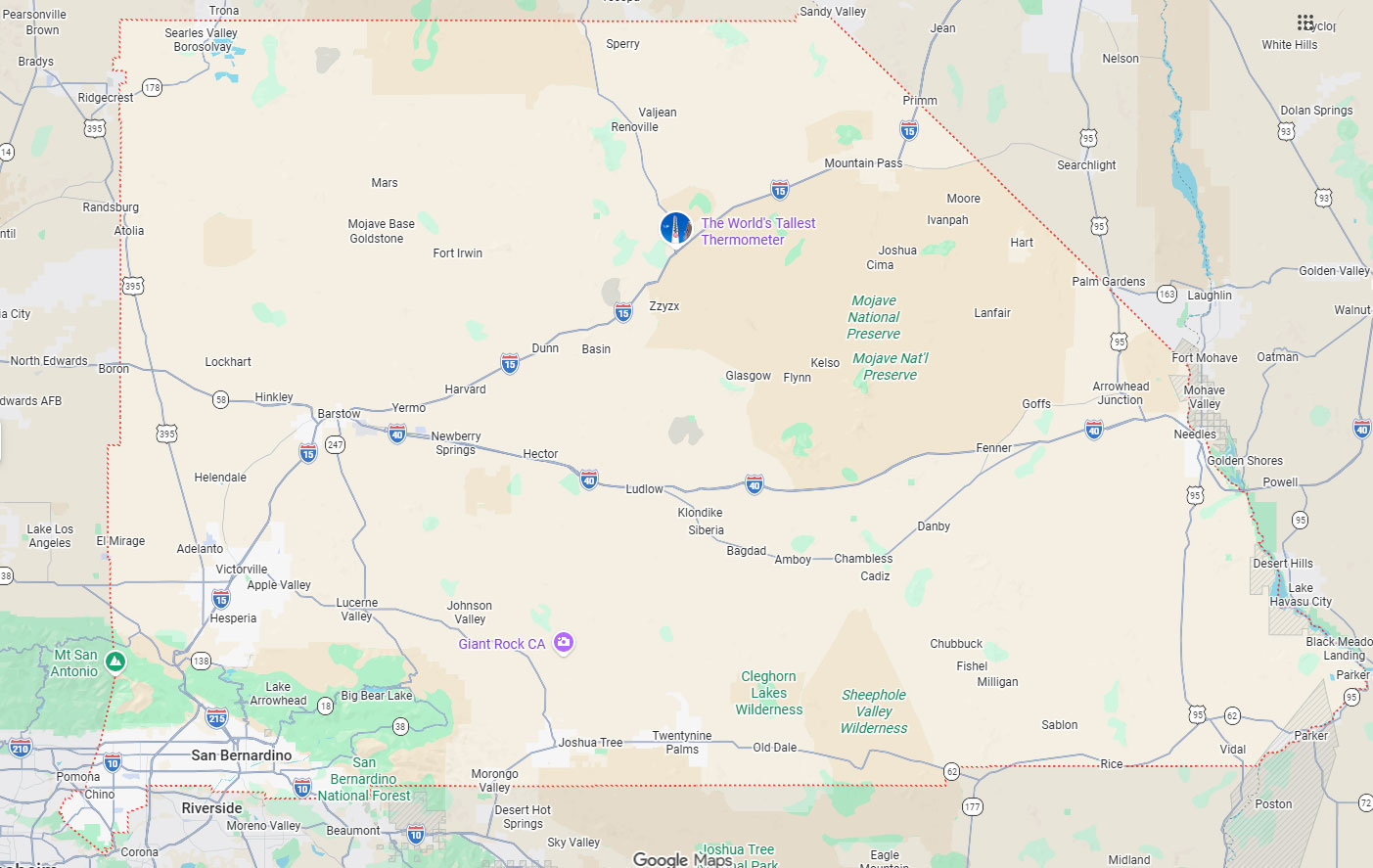
Bess Utility Solutions has 29 years in business and more than 1,000 clients across California, Arizona, and Nevada. Offices in Hayward, Fresno, Ontario and Orange, Sacramento, and Phoenix support local project coordination.
Crews across the Bay Area, Central Valley, Northern California, and Phoenix markets are trained in FHWA Quality Level B surface geophysics and Quality Level A exposure. CPUC-certified MBE and DBE status supports public agency contracting.
Project teams can request a quote, book a pre-construction consultation, or talk through scope and scheduling directly. Early contact lets Bess review plans, assess constraints, recommend methods, and line up traffic control or access.
Quotes are built around scan areas, linear footage for locating, pothole counts, survey deliverables, and timing. Defining scope and confidence levels up front prevents surprises later.
FHWA and Purdue studied 71 projects across Virginia, North Carolina, Texas, and Ohio with construction costs above $1 billion, and reported $4.62 in quantified savings for every $1.00 spent on SUE.
San Francisco's aging infrastructure, constrained jobsites, and public sensitivity to disruption make early scanning and locating especially valuable. The workflow of detect, interpret, mark and map, verify, excavate, and cut safely builds confidence in stages and supports informed risk management.
Bess Utility Solutions pairs current locating equipment with trained field crews and integrated services to cut subsurface uncertainty for Bay Area teams. On tenant improvements, seismic retrofits, tie-ins, or municipal work, early investigation protects the schedule, the budget, and the crew.
If you have a slab to core, a trench to open, or a retrofit that touches unknown lines, get the scan done before the crew mobilizes. Bess Utility Solutions brings 29 years of field work, more than 1,000 clients across California, Arizona, and Nevada, and CPUC-certified MBE and DBE status for public agency contracting. Crews work to FHWA Quality Level B and Quality Level A methods, so you get a marked plan and, where stakes call for it, an exposed line you can see.
Call the Hayward office at (408) 988-0101 to talk through scope, access, and scheduling, or request a quote online, and a project manager will follow up with pricing and a mobilization window. Send plans or a site sketch with the request, and we will tell you which combination of scanning, locating, and potholing fits the work.
A. Depth depends on soil type, moisture, and target size rather than a fixed number. Dry sand and gravel can return useful data several feet down, while clay, saturated fill, and saltwater intrusion near the bay cut that range sharply. In concrete, scanning usually covers the first several inches to about 18 inches, enough for rebar, tendons, and conduit in most slabs. A technician gives you the working depth after the first passes rather than promising one in advance.
A. No. 811 notification is required and stays part of the process on every job. Public notification covers member-owned lines, so private lines, abandoned pipes, non-conductive utilities, and anything embedded in a slab can go unmarked. Private locating with GPR and electromagnetic equipment fills those gaps, and potholing confirms what the marks mean before a machine digs.
A. Pricing follows scope rather than a flat rate. The drivers are scan area or linear footage, the number of core locations, site access and traffic control, after-hours work in occupied buildings, and whether you need mapped deliverables or potholing. Same-week mobilization also affects the number. Send the scan area and a target date, and the quote will list those items separately.
A. Routine concrete scanning on one floor often takes a few hours once the area is clear. Locating across a site or street frontage usually runs a half day to a full day, depending on footage, congestion, and traffic control. Bay Area mobilization from Hayward is often available within a few business days, and urgent locates sooner. Clearing furniture, vehicles, and stored material before arrival keeps the visit short.
A. Often yes, because GPR responds to a contrast in electrical properties rather than to metal. PVC, clay, and concrete pipe show up when the surrounding soil differs enough, and the line is not too deep or too small. Electromagnetic locating cannot trace those lines because they carry no signal, which is why the two methods run together. When a plastic or abandoned line sits in the dig footprint, vacuum excavation confirms position, size, and condition.