Conductivity determines feasibility: Electrical conductivity is the primary factor limiting GPR depth. Wet clay's high conductivity (100-1000+ mS/m) restricts penetration to less than 1 meter, while dry sand's low conductivity (<0.01 mS/m) enables 10-50 meters of depth.
Moisture transforms performance: Water saturation increases both dielectric constant and conductivity, turning favorable materials like sand into poor performers, especially in coastal areas where dissolved salts amplify the effect.
Frequency selection is critical: Lower frequencies (25-250 MHz) penetrate deeper in conductive soils but sacrifice resolution, while higher frequencies (500-2600 MHz) provide detailed imaging at shallow depths in resistive materials.
Clay content exceeding 15-20% severely limits GPR: Even moderate clay presence dramatically reduces penetration depth, often requiring alternative geophysical methods like Electrical Resistivity Tomography.
Calibration ensures accuracy: Ground-truth calibration using known buried objects is essential to achieve ±10-15% depth accuracy, as incorrect velocity assumptions create systematic errors throughout the survey.
Ground-Penetrating Radar technology has revolutionized subsurface investigation across industries from utility locating to archaeology, but its effectiveness isn't universal. The difference between detecting a utility line at 15 meters depth and failing to penetrate beyond 30 centimeters often comes down to one factor: soil conditions. Understanding the soil impact on GPR performance, particularly how clay, sand, rock, and asphalt affect ground‑penetrating radar accuracy, is essential for anyone planning a subsurface survey.
This comprehensive guide explains the electrical properties that govern GPR performance and provides practical strategies for achieving reliable results in challenging soil environments.
What Is Ground Penetrating Radar (GPR) And How Does It Work?
GPR sends electromagnetic waves into the ground and measures the reflections that bounce back from subsurface boundaries. The system records the two-way travel time of these signals, then converts that timing into depth measurements based on the material's electrical properties.
Core Principles of GPR Technology
Key Concept
Description
Technical Detail
Signal Transmission
GPR sends high-frequency electromagnetic waves into the subsurface
Common frequencies: 25 MHz to 2.6 GHz
Reflection
EM waves reflect at boundaries between materials with different electrical properties
Reflection strength proportional to dielectric contrast
Reception
Reflected waves are received and converted to two-way travel time
Travel time converted to depth using material velocity
Core Process
Non-destructive geophysical method imaging subsurface features
Relies on propagation and reflection of high-frequency EM waves
Why Soil Conditions Are Critical to GPR Measurements:
Signal attenuation control: Electrical conductivity (σ) controls attenuation or loss of EM wave energy; high conductivity causes rapid energy conversion to heat, severely reducing penetration depth
Wave velocity determination: Dielectric permittivity (εr or K) controls velocity according to v = c / √εr, where c is the speed of light in vacuum; a higher dielectric constant results in slower wave velocity
Depth calculation dependency: Dielectric constant is the primary factor used to convert two-way travel time into estimated depth
Inverse exponential relationship: As conductivity increases, GPR signal is attenuated more rapidly with an inverse and exponential relationship, making conductivity the main limiter in highly conductive environments
How Do Soil Properties Affect GPR Accuracy?
Two fundamental properties govern GPR performance: dielectric permittivity controls how fast signals travel, while electrical conductivity determines how quickly signals lose strength. Moisture content affects both properties simultaneously, making it the single most influential variable in GPR surveys.
Key Soil Properties Impacting GPR
Property
GPR Impact
Technical Specification
Dielectric Permittivity (εr)
Controls wave velocity and wavelength
Primary factor for depth conversion from travel time
Electrical Conductivity (σ)
Controls signal attenuation/energy loss
Measured in milliSiemens/meter (mS/m); primary limiter of penetration
Moisture Content
Affects both dielectric constant and conductivity
Pure water εr ≈ 80 vs. dry soil minerals εr ≈ 3-10
Density
Influences signal penetration capability
Dense soils cause stronger reflections, limiting depth
Porosity
Affects radar wave propagation
More pore spaces (air gaps) allow easier wave travel
How Soil Moisture Influences GPR Results:
Dielectric constant increase: Water's high dielectric constant (εr ≈ 80) is significantly higher than dry soil minerals (εr ≈ 3-10), causing moisture to rapidly increase the bulk soil dielectric constant
Wave velocity reduction: Increased moisture slows wave velocity and reduces wavelength through the relationship v = c / √εr
Conductivity amplification: Water containing dissolved salts or minerals dramatically increases soil pore water conductivity (σ), causing a massive signal attenuation increase
Moisture estimation application: The effect is quantifiable using models like Topp's equation for soil moisture estimation
Soil Density and Conductivity Effects on Signal Attenuation:
Dense soil performance: Dense soil types (clay, shale) with high moisture and mineral content lead to high conductivity, often limiting penetration to less than 1 meter
Low-density advantage: Less dense soils (dry sand, gravel) with low conductivity allow deep penetration up to 50+ meters
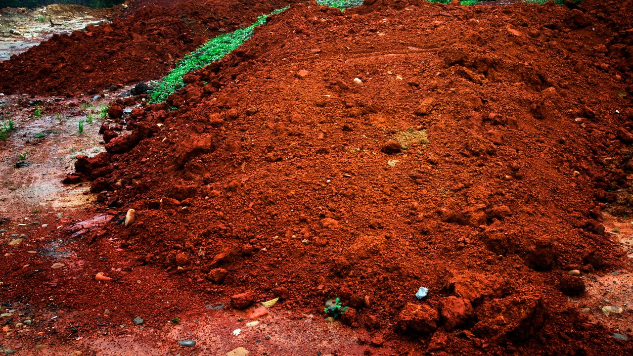
Clay soil is GPR's worst enemy. Its high electrical conductivity, driven by bound water and mobile ions, absorbs radar energy within the first meter. Understanding clay interference with GPR signals is critical for survey planning, surveys in clay-rich environments often fail completely or require low-frequency antennas that sacrifice resolution for minimal depth gain.
Clay Soil Characteristics Impacting GPR
Characteristic
Value/Effect
GPR Impact
Dielectric Constant
5-40 (wet clay: 25-40)
High values slow wave velocity significantly
Electrical Conductivity
100-1000+ mS/m (wet)
Extremely high attenuation
Signal Attenuation
50-300+ dB/m
Severe signal loss
Typical Penetration Depth
Often < 1 meter
Poor to extremely poor performance
Clay Content Threshold
>15-20% clay content
Severely depth-limited surveys
Why Clay's High Water Content Interferes with GPR Signals:
Cation Exchange Capacity (CEC): Clay minerals, particularly montmorillonite with high CEC, are highly conductive due to bound water and mobile ions on large surface areas
Small increases, major impacts: Even small increases in clay content can drastically reduce GPR penetration depth
Practical limitation: GPR surveys in soils with greater than 15-20% clay content are often severely depth-limited, sometimes to less than one meter
Water retention effect: Clay's ability to retain water creates persistently high moisture content, leading to sustained high conductivity
Clay's Electrical Conductivity Effects on GPR:
Conductivity range: Wet clay exhibits 100-1000+ mS/m conductivity compared to dry sand at 0.001-0.01 mS/m
Attenuation severity: Attenuation rates of 50-300+ dB/m make wet clay one of the worst materials for GPR penetration
Coastal area challenges: Water-saturated soils with high mineral content (coastal areas) are poor GPR environments due to combined moisture and salt effects
Case study evidence: Urban utility locating in clay-rich backfill saturated by a broken water main made it impossible to locate utilities at 1-2 meters depth; signal attenuated within the first 30 cm
How Does Sand Soil Affect GPR Accuracy?
Sand is GPR's ideal medium. Its low conductivity and high porosity allow radar signals to travel deep with minimal energy loss. Dry sand detection capabilities routinely achieve 10-20 meters of penetration, with exceptional conditions yielding 50+ meters, making it the gold standard for subsurface imaging.
Sand Soil Unique Features for GPR
Feature
Value/Characteristic
GPR Advantage
Dielectric Constant (Dry)
3-5
Low value allows faster wave velocity
Electrical Conductivity (Dry)
0.001-0.01 mS/m
Minimal signal attenuation
Signal Attenuation (Dry)
< 1 dB/m
Excellent signal preservation
Maximum Penetration Depth
10-20m (can exceed 50m in ideal conditions)
Among the best materials for GPR
Porosity
High air space content
Enhances wave propagation
Low Moisture Content Effects in Sand:
Deep penetration capability: Dry sand allows for penetration depths of 10-20 meters, with some sources citing up to 50+ meters in optimal conditions
Minimal attenuation: Attenuation less than 1 dB/m enables signal to travel much farther compared to conductive soils
Water saturation impact: When saturated, sand's dielectric constant increases to 25-30 and conductivity rises to 10-100 mS/m, significantly reducing performance
Seasonal consideration: Surveys during dry seasons maximize sand's favorable characteristics
Sand Porosity Enhancing GPR Signal Propagation:
Air pocket advantage: High porosity creates more air spaces (εr ≈ 1) that allow radar waves to pass through more easily
Reduced absorption: Compared to denser soils, sand exhibits significantly reduced signal absorption
Uniform texture benefit: Consistent particle size results in clearer, more interpretable signal readings with less scattering
Archaeological success: Dry, sandy sites yield excellent GPR results for mapping ancient foundations and burial features
How Does Rock Affect GPR Accuracy?
Rock performance in GPR surveys varies dramatically by type and condition. Solid, dry crystalline rock like granite offers exceptional penetration exceeding 100 meters, while fractured or weathered zones create complex reflections that complicate interpretation. The key differentiator is rock density and moisture content.
Rock Features Influencing GPR Accuracy
Rock Feature
Specification
GPR Effect
Dielectric Constant
4-10 (typical rock)
Relatively low, similar to dry soils
Density (Granite/Basalt)
Very high
Reflects most radar signal, shallow penetration in dense formations
Density (Sandstone)
Lower
Allows more GPR wave penetration
Penetration (Granite/Limestone)
Up to 100+ meters (when dry)
Excellent in solid, dry formations
Conductivity
Low (when dry)
Minimal attenuation in resistive rock
Rock Composition and Density Impact on Signal Reflection:
Dense rock performance: Dense rock types like granite and basalt reflect most of the radar signal, potentially leading to shallow penetration in fractured or weathered zones
Optimal conditions: Solid, dry rock formations (granite, limestone) offer excellent penetration up to 100+ meters due to low conductivity
Softer rock advantage: Softer rock types like sandstone allow for more GPR wave penetration compared to crystalline rocks
Bedrock interface: The interface between wet, conductive overburden and solid bedrock creates strong dielectric contrast, resulting in clear, high-amplitude reflection that defines depth to bedrock
Fractures and Voids in Rock Affecting GPR Interpretation:
Signal scattering: Voids, fractures, and air gaps create significant dielectric contrast (air εr ≈ 1 vs. rock εr ≈ 4-10), causing strong reflections and signal scatter
Multiple reflections: GPR may pick up multiple overlapping reflections from fracture networks, creating complexity in depth and structure interpretation
Detection capability: This same property makes GPR highly effective for detecting voids, sinkholes, and delaminations in concrete structures
Archaeological application: Air-filled voids and burial features provide strong, easily detectable reflections in bedrock environments
How Does Asphalt Affect GPR Accuracy?
Asphalt behaves similarly to dry concrete, offering moderate GPR performance with typical penetration around 2.5 meters. Understanding rock and asphalt effects on GPR is crucial for utility detection services. Urban pavement surveys face additional challenges from multiple subsurface layers, dense utility networks, and moisture infiltration that degrades electrical properties and reduces signal clarity.
Asphalt Characteristics Affecting GPR
Characteristic
Value
GPR Impact
Dielectric Constant
3-5
Similar to dry sand
Typical Penetration Depth
2.5 meters
Moderate depth capability
Conductivity
Variable (0.001-0.01 mS/m when dry)
Depends on composition and moisture
Density
High (when compacted)
Causes stronger signal reflection
Asphalt Thickness and Density Affecting Signal Reflection:
Layer thickness impact: Thicker asphalt layers reflect more GPR signals, limiting the depth of penetration into underlying materials
High-density reflection: High-density asphalt causes more signal reflection at the surface, reducing GPR effectiveness for imaging deeper layers
Dry concrete comparison: Similar to dry concrete (εr = 6-8, conductivity 0.001-0.01 mS/m), asphalt provides relatively good GPR conditions when dry
Moisture degradation: Presence of moisture from leaking infrastructure or de-icing salts significantly increases conductivity and reduces penetration
Urban Asphalt Challenges for GPR:
Multi-layer complexity: Urban infrastructure includes multiple layers of asphalt, concrete, and utilities, making GPR readings more complicated with overlapping reflections
Cultural noise: Dense networks of utilities (pipes, cables, rebar) create complex, overlapping hyperbolic reflections difficult to resolve, especially in 2D surveys
Surface interference: Asphalt layers may reflect and interfere with GPR signals, causing noisy data or poor depth resolution for deeper targets
Bridge deck case: Near expansion joints where de-icing salts penetrate concrete, high salt content increases conductivity, causing rapid signal attenuation (though this indicates chloride contamination zones)
What Challenges Do Different Soil Types Pose For GPR Accuracy?
Subsurface heterogeneity is GPR's primary interpretation challenge. Mixed soil layers, moisture gradients, and compositional changes create velocity variations that complicate depth calculations and introduce artifacts. Understanding these challenges is essential for accurate survey design and data interpretation.
Soil Layer Variations Affecting GPR Results
Variation Type
Effect on GPR
Measurement Impact
Layer Depth Changes
Different penetration at each layer
Variable signal strength with depth
Layer Composition
Changes in dielectric properties
Alters wave speed and reflection characteristics
Soil Heterogeneity
Mixed or layered soil types
Inconsistent signal readings, velocity variations
Moisture Gradients
Gradual vs. sharp water table transitions
Clear reflections in sand, gradual/invisible in clay
Soil Heterogeneity Impacting Signal Penetration:
Wave speed variation: Mixture of soil types causes variation in wave propagation speed, requiring different velocity assumptions for depth calculation
Differential attenuation: Non-homogeneous soils result in different attenuation rates across the survey area, with some zones penetrating deeply while others fail at shallow depth
Water table detection: In sandy aquifer, water table creates sharp boundary between dry sand (low εr) and saturated sand (high εr) with clear reflection; in clay, water table is gradual transition that may be undetectable
Archaeological interference: Features like ancient kilns alter magnetic and electrical properties of surrounding soil, creating highly conductive, attenuating zones that mask deeper features
Common GPR Issues in Clay, Sand, Rock, and Asphalt:
Clay limitations: Penetration often less than 1 meter in wet clay; surveys with >15-20% clay content severely depth-limited; urban utility locating can fail completely when clay is water-saturated
Sand variables: While dry sand offers 10-50m penetration, saturated sand with salt content (coastal areas) can reduce effectiveness to fair/poor levels with conductivity reaching 10-100 mS/m
Rock challenges: Dense crystalline rocks reflect signals at surface; fractured zones create multiple overlapping reflections; heterogeneous rock types cause velocity calculation errors
Asphalt/urban complexity: Multiple material layers (asphalt over concrete over soil); dense utility networks create hyperbola "clutter"; metallic infrastructure causes shadowing effects
Shadowing effect: Metal objects (rebar mats, large utility pipes) reflect nearly all GPR energy, preventing signal penetration and creating "shadow zones" where deeper targets are completely obscured
Resolution degradation: Minimum detectable object size is approximately 1/4 wavelength; rule of thumb suggests reliable detection requires object diameter of at least 10% of burial depth
How Can GPR Accuracy Be Improved In Different Soil Conditions?
Success in challenging environments requires matching equipment and methods to subsurface conditions. Strategic antenna selection, proper calibration, and advanced processing techniques can significantly improve GPR performance even in difficult soils. For specialized applications like utility locating in frozen soil, understanding seasonal variations is equally important.
Best Practices for GPR in Different Soil Types:
Clay soil strategy: Use lower frequency antennas (100-250 MHz) to achieve greater depth penetration, accepting trade-off of lower resolution; consider alternative methods (Electrical Resistivity Tomography) when clay content exceeds 20%
Sand soil optimization: Higher frequency antennas (500-1000 MHz) for shallow, high-resolution scans in dry sand; conduct surveys during dry seasons to maximize favorable conditions
Rock applications: Use specialized frequency ranges based on investigation depth: 25-50 MHz for deep geological studies (20-80m), 100-250 MHz for bedrock mapping (10-20m)
Asphalt/concrete: High-frequency antennas (750-2600 MHz) for structural inspection; adjust sensitivity settings to deal with surface reflections from multiple material layers
Frequency-Application-Depth Reference:
Frequency (MHz)
Max Penetration (m)
Resolution (m)
Typical Application
25
40-80
0.5-1.0
Deep geological studies, glaciology
50
20-40
0.25-0.5
Bedrock mapping, deep utility location
100
10-20
0.1-0.25
Shallow geological, large utility location
250
4-8
0.05-0.1
Utility locating, archaeology
500
2-4
0.025-0.05
Concrete scanning, pavement assessment
750
1.5-2.7
0.015-0.03
Concrete scanning, rebar mapping
1000
1-2
0.01-0.025
High-resolution concrete scanning
Calibration Methods for Challenging Soil Types:
Ground truth calibration: Use known buried objects (rebar layer, excavated pipe) to determine actual velocity and validate depth calculations; essential when depth accuracy is critical
Hyperbola fitting: Analyze the theoretical hyperbolic shape against the observed reflection using specialized software to calculate an accurate velocity for specific target and depth
Common Midpoint (CMP) surveys: Specialized survey technique that measures velocity changes with depth, accounting for layered soil conditions
Depth accuracy expectations: Typical accuracy is ±10-15% of true depth, can vary from ±5% to ±20% depending on site conditions and calibration quality
Velocity determination: Critical because GPR calculates depth from travel time using v = c / √εr; incorrect dielectric constant leads to systematic depth errors throughout survey
Technological Innovations Enhancing GPR in Varied Soils:
Multi-frequency systems: Deploy multiple antenna frequencies simultaneously to balance depth penetration and resolution across heterogeneous soil profiles
Advanced signal processing: Compensate for attenuation using gain adjustments, filtering techniques, and migration algorithms to enhance target visibility in challenging conditions
3D GPR surveys: Replace 2D transects with dense grid surveys to resolve complex utility networks and reduce ambiguity from overlapping hyperbolic reflections
Industry standards compliance: ASTM D6432 provides a framework for equipment, field procedures, and data processing, but explicitly notes method is site-specific based on subsurface electrical properties
Soil Conditions That Control GPR Accuracy
GPR performance is governed by dielectric permittivity (εr), which affects wave speed, and especially electrical conductivity (σ), which drives signal attenuation and is the main limiter on depth—hence wet clay can restrict penetration to under a meter while dry sand and competent rock can allow tens of meters. Moisture and dissolved salts can quickly turn otherwise favorable ground into poor GPR conditions, and antenna choice must balance depth versus resolution (lower frequencies for deeper, larger targets; higher frequencies for shallow, small targets). Evaluating soil type early helps determine whether GPR is feasible, select the right frequency, calibrate velocity for reliable depth estimates, and decide when alternative methods like electrical resistivity or electromagnetic induction are more appropriate.
No. GPR depth and clarity depend mainly on soil electrical conductivity: highly conductive wet clay can limit penetration to <1 m or make surveying infeasible, while low-conductivity dry sand and competent rock can allow 10–100+ m. Moist, intermediate soils (e.g., loam) typically yield moderate results.
What Are the Most Challenging Soil Conditions for GPR?
Wet clay-rich soils, saline/coastal soils, and water-saturated fine-grained sediments are the hardest because high conductivity and moisture rapidly attenuate the signal, sometimes reducing penetration to centimeters. Strong layering/heterogeneity can also distort velocity and depth estimates, and dense metallic environments (utilities, rebar) can shadow deeper targets.
How Do I Mitigate Signal Loss When Using GPR in Clay, Sand, Rock, or Asphalt?
Use lower frequencies (≈100–250 MHz) in clay and survey during drier conditions, supplementing with resistivity methods when clay is high. Use higher frequencies (≈500–1000 MHz) in dry sand for better detail, but avoid salty/wet coastal zones. In rock, match frequency to depth (≈25–50 MHz deep, 100–250 MHz mapping) and consider 3D in fractured areas. For asphalt, use very high frequencies (≈750–2600 MHz) and careful processing, and always calibrate velocity and depth with known targets or ground truth.
We prioritize clear communication and reliable solutions to meet your specific requirements. Get in touch with us today, and let's work together to ensure the safety and efficiency of your projects.
We prioritize clear communication and reliable solutions to meet your specific requirements. Get in touch with us today, and let's work together to ensure the safety and efficiency of your projects.