Hayward, CA
Fresno, CA
Orange, CA
Sacramento, CA
Phoenix, AZ
Key Takeaways
Ground-penetrating radar reveals what lies beneath the surface without digging. This non-invasive technology sends electromagnetic waves into the ground and maps the subsurface by analyzing the signals that bounce back. Understanding how GPR technology works, its capabilities, and its limitations is essential for anyone using this technology for utility locating, construction planning, archaeological surveys, or infrastructure assessment.
This comprehensive guide breaks down radar basics and GPR fundamentals: how the technology operates, what it can and cannot detect, which soil conditions affect accuracy, and what the future holds for this versatile geophysical method. For professional subsurface investigation services, expert guidance ensures accurate results tailored to your project's unique conditions.
Ground‑penetrating radar is a geophysical imaging method that uses high-frequency electromagnetic waves (25 MHz to 2.6 GHz) to detect and map subsurface features without excavation. The system measures reflections from boundaries between materials with different electrical properties, such as soil and buried pipes, concrete and rebar, or rock layers.
Define Ground-Penetrating Radar (GPR): GPR transmits electromagnetic pulses into the ground and records reflections from subsurface targets. The technology excels at locating buried utilities (especially non-metallic pipes like PVC and fiber optic conduits), mapping archaeological features, inspecting concrete structures, assessing pavement conditions, and conducting environmental investigations. Unlike metal detectors or electromagnetic induction tools, GPR detects both metallic and non-metallic objects by sensing changes in material properties rather than just metal content. These radar basics form the foundation of modern subsurface imaging applications.
Describe the Purpose of GPR: GPR serves critical functions across multiple industries. In utility locating, it finds buried infrastructure before excavation. In archaeology, it maps ancient structures without disturbing sites. In construction, it reveals rebar, conduits, and voids within concrete. In environmental work, it tracks contamination plumes and maps geological features. The method's primary advantage is real-time subsurface imaging without physical intrusion.
GPR Compared to Other Surveying Techniques: GPR differs fundamentally from electromagnetic (EM) induction, which only detects conductive metals. While EM locators excel at finding metallic utilities, GPR detects plastic pipes, concrete structures, voids, and geological features. In highly conductive soils (wet clay, saline conditions), GPR performance degrades significantly, and situations where Electrical Resistivity Tomography (ERT) or magnetometry may prove more effective. GPR's strength lies in resistive environments where signal attenuation remains low.
GPR operates by transmitting electromagnetic pulses into the subsurface and measuring the time it takes for reflections to return. The system converts these travel times into depth measurements using the electromagnetic wave velocity in the ground material.
How GPR Uses Electromagnetic Waves to Detect Objects: A GPR antenna emits high-frequency electromagnetic pulses that propagate through subsurface materials at velocities determined by the material's dielectric permittivity (εᵣ). Wave velocity follows the relationship: v = c / √εᵣ, where c equals the speed of light in vacuum. When waves encounter boundaries between materials with different dielectric constants, such as dry soil (εᵣ ≈ 4) meeting a PVC pipe (εᵣ ≈ 3) or concrete (εᵣ ≈ 6) containing air voids (εᵣ ≈ 1), a portion of the energy reflects back to the surface. The receiving antenna captures these reflections, and the system calculates depth by multiplying half the two-way travel time by the wave velocity.
Process of GPR Signal Reflection: Reflection strength depends on dielectric contrast, the difference in electrical properties between the target and the surrounding material. Metal objects create the strongest reflections because they act as perfect reflectors with an effectively infinite dielectric constant. Air voids also produce strong signals due to the sharp contrast with surrounding materials.
Conversely, targets with similar dielectric properties to their host medium (like a concrete pipe in limestone) generate weak reflections that may be undetectable. The dielectric constant serves as the critical parameter for converting measured travel time into accurate depth estimates.
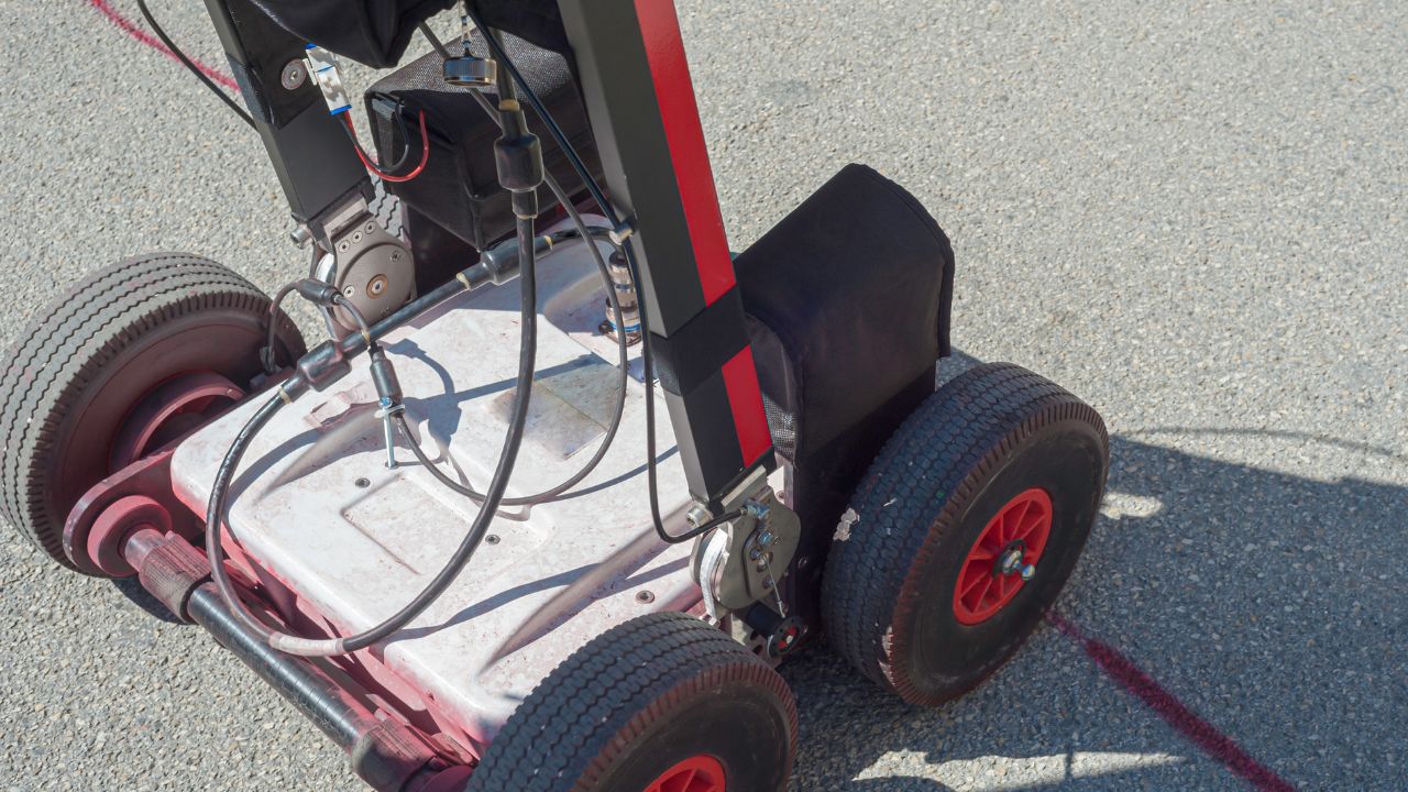
A GPR system consists of four primary components working together to generate subsurface imaging results. Each component plays a specific role in signal transmission, reception, processing, and display.
Antenna (Transmitter and Receiver): Emits electromagnetic pulses and receives reflected signals. Configurations include monostatic designs (combined transmitter/receiver in one unit) and bistatic designs (separate transmitter and receiver units). Antenna frequency determines both penetration depth and resolution.
Control Unit: Processes incoming signals, manages data collection parameters, converts two-way travel times into depth measurements, and applies signal processing techniques to enhance data quality.
Display/Recording System: Generates radargrams, visual representations of subsurface data where depth appears on the vertical axis and survey position on the horizontal axis. Reflections appear as hyperbolic patterns that reveal buried object locations.
Power Supply: Provides energy for system operation during field surveys, typically through rechargeable batteries for portable units.
Antenna frequency creates a fundamental trade-off: lower frequencies penetrate deeper but provide lower resolution; higher frequencies offer high resolution but shallow penetration. A 25 MHz antenna may reach 40-80 meters depth but only resolves objects larger than 0.5-1.0 meters, making it suitable for deep geological studies. A 1000 MHz antenna penetrates just 1-2 meters but detects objects as small as 0.01-0.025 meters, ideal for high-resolution concrete scanning and rebar mapping.
The minimum detectable object size equals approximately one-quarter of the signal's wavelength in the medium. A practical field rule states that GPR reliably detects objects with diameters of at least 10% of their burial depth. This means a target buried at 5 meters depth must be at least 0.5 meters in size to ensure detection. Resolution degrades with depth because the signal wavelength lengthens as it travels through the subsurface, making small deep objects undetectable regardless of antenna frequency.
| Antenna Center Frequency (MHz) | Approx. Max Penetration Depth (m) | Suitable Target Size (Resolution) (m) | Typical Application |
| 25 | 40-80 | 0.5-1.0 | Deep geological studies, glaciology |
| 50 | 20-40 | 0.25-0.5 | Bedrock mapping, deep utility location |
| 100 | 10-20 | 0.1-0.25 | Shallow geological, large utility location |
| 250 | 4-8 | 0.05-0.1 | Utility locating, archaeology |
| 500 | 2-4 | 0.025-0.05 | Concrete scanning, pavement assessment |
| 750 | 1.5-2.7 | 0.015-0.03 | Concrete scanning, rebar mapping |
| 1000 | 1-2 | 0.01-0.025 | High-resolution concrete scanning |
GPR serves diverse industries requiring subsurface information without excavation. Applications range from finding buried utilities to mapping archaeological sites, inspecting concrete structures, and detecting environmental hazards.
Utility Locating and Civil Engineering: Mapping underground utilities represents GPR's most common application. The technology excels at locating non-metallic pipes (PVC, concrete, fiber optic conduits) that electromagnetic induction cannot detect. Urban environments present complex challenges, disturbed soils, multiple utility corridors, and varying backfill materials. Operators typically deploy 250 MHz antennas in moderately conductive soils to balance penetration depth with resolution, though highly conductive wet clay can limit effectiveness to less than one meter depth.
Archaeological Site Investigations: GPR successfully maps non-metallic features like ancient foundations, burial pits, ditches, and disturbed soil patterns without disturbing sites. The method has revealed Roman villa remains and prehistoric settlements in dry, sandy, or loamy soils where dielectric contrast remains high. Archaeological surveys often combine GPR with magnetometry or resistivity methods in clay-rich or highly mineralized areas where GPR performance degrades. Success depends heavily on soil moisture; dry conditions yield clear results while wet sites often fail.
Concrete Inspection and Structural Assessment: High-frequency antennas (1.0-2.6 GHz) provide detailed images of rebar, conduits, post-tension cables, and voids within concrete structures. Bridge deck inspections commonly use GPR to assess structural integrity and map corrosion-prone areas. Dry concrete offers excellent penetration, but moisture from leaking roofs or de-icing salts increases conductivity and limits depth. Paradoxically, this signal attenuation itself indicates chloride contamination and potential corrosion, turning a limitation into diagnostic information.
Environmental Hazard Detection and Geological Assessment: GPR maps water tables, delineates soil horizons, and tracks contaminant plumes in favorable geology. Sandy aquifers produce sharp dielectric boundaries at the water table, creating clear reflections. The technology excels in permafrost studies and glaciology, where frozen ground (ice εᵣ ≈ 3-4) allows penetration depths exceeding 100 meters. Clay-rich environments present significant challenges; high background conductivity often prevents the signal from reaching the water table.
Forensic and Crime Scene Analysis: GPR detects burial features and disturbed soil patterns using principles similar to archaeological applications but with different investigative contexts. The method provides non-invasive screening of suspected burial sites, though success rates depend entirely on soil conditions and the dielectric contrast between disturbed and undisturbed material.
GPR offers significant operational benefits that make it the preferred choice for many subsurface investigations. The technology's non-destructive nature and real-time capabilities distinguish it from traditional excavation methods.
Key Advantages:
GPR performance depends fundamentally on subsurface electrical properties. Understanding these limitations prevents unrealistic expectations and survey failures.
Electrical conductivity governs GPR effectiveness; high conductivity rapidly absorbs electromagnetic energy, severely limiting penetration depth. The dielectric permittivity (εᵣ) controls wave velocity and affects depth calculations, while conductivity (σ) determines signal attenuation and maximum survey depth.
| Material | Dielectric Constant (K) | Conductivity (mS/m) | Attenuation (dB/m) | GPR Performance |
| Dry Sand | 3-5 | 0.001-0.01 | <1 | Excellent penetration (up to 10-20m) |
| Dry Concrete | 6-8 | 0.001-0.01 | <1 | Excellent penetration (for structural work) |
| Moist Loam | 10-20 | 1-10 | 5-15 | Good to Fair penetration |
| Saturated Sand | 25-30 | 10-100 | 10-30 | Fair penetration (depth limited) |
| Wet Clay | 25-40 | 100-1000+ | 50-300+ | Poor penetration (often <1m) |
| Saltwater | 80 | 1000+ | 300+ | Extremely poor penetration (centimeters) |
Clay content above 15-20% often limits penetration to less than one meter due to high conductivity from bound water and mobile ions.
Moisture content dramatically affects performance; water's high dielectric constant (εᵣ ≈ 80) increases bulk soil permittivity while dissolved minerals increase conductivity.
Salt and mineral content (chlorides, pyrite) create extreme conductivity that absorbs signals within centimeters.
Frozen ground provides excellent GPR conditions (ice εᵣ ≈ 3-4), but thawing causes sharp increases in both permittivity and conductivity, suddenly collapsing penetration depth.
These conditions don't prevent GPR use but require experienced interpretation to distinguish real targets from artifacts.
GPR depth accuracy typically falls within ±10-15% of true depth, though this varies from ±5% to ±20% depending on site conditions and calibration methods. Accuracy depends primarily on determining the correct electromagnetic wave velocity in subsurface materials.
Accuracy degrades with depth due to the cumulative effects of material heterogeneity and signal attenuation.
Accurate results require ground truthing with known depths, specialized velocity analysis techniques, and recognition that a single velocity value rarely applies to entire heterogeneous survey areas.
GPR technology advances rapidly through integration with artificial intelligence, improved sensor designs, and autonomous platforms. These developments promise to expand GPR capabilities while reducing interpretation complexity and operational costs.
Artificial intelligence and machine learning are transforming GPR data interpretation by automating pattern recognition in radargrams. Algorithms trained on thousands of survey datasets can distinguish actual targets from false positives caused by soil heterogeneity, reducing interpretation time and human error. Machine learning models identify characteristic hyperbolic patterns, classify buried objects by reflection signatures, and flag anomalies requiring expert review.
These technologies increase survey efficiency while improving accuracy, particularly for less experienced operators. AI-assisted interpretation doesn't replace field expertise but augments it, combining automated screening with human judgment for complex scenarios.
Sensor technology improvements enable greater depth penetration without sacrificing resolution, previously an unavoidable trade-off. Higher-frequency antennas with advanced signal processing deliver enhanced shallow imaging for concrete scanning and rebar mapping. Specialized antenna designs optimize performance for specific applications: ultra-high-frequency arrays for detailed structural assessment, wide-bandwidth systems for archaeological surveys, and multi-frequency units that adapt to varying site conditions.
Integration of multiple frequency systems in a single device provides field versatility, allowing operators to switch between deep reconnaissance and high-resolution imaging without changing equipment.
Drone-mounted GPR systems increase survey speed and accessibility for large-area geological and environmental assessments. Aerial platforms cover terrain that ground-based systems cannot reach, such as steep slopes, wetlands, and hazardous sites. Robotic GPR platforms automate surveys in dangerous environments (contaminated sites, unstable structures, post-disaster zones) while maintaining consistent survey patterns that reduce human variability.
Autonomous systems equipped with GPS and inertial navigation collect precisely georeferenced data, improving accuracy for repeat surveys and monitoring temporal changes. These platforms don't replace traditional GPR but expand operational contexts and increase survey efficiency.
Ground-penetrating radar delivers powerful non-destructive subsurface imaging across utility locating, archaeology, concrete inspection, and environmental monitoring. Success depends fundamentally on subsurface electrical properties, specifically soil conductivity and dielectric contrast. GPR excels in dry, non-conductive media (sand, gravel, granite, ice) where signals penetrate deeply with minimal attenuation. Performance collapses in highly conductive environments (wet clay, saltwater, saline soils) where penetration often drops below one meter. Depth accuracy typically ranges ±10-15% with proper calibration but requires accurate material property knowledge and ground truthing for reliable results.
GPR technology continues evolving through artificial intelligence integration, advanced sensor designs, and autonomous platforms, expanding capabilities in infrastructure management, environmental monitoring, and archaeological preservation. Industry standards like ASTM D6432 provide procedural frameworks, but survey success remains site-dependent. Practitioners must combine technical knowledge with field experience to predict feasibility, select appropriate equipment, and manage expectations. Understanding both GPR's capabilities and limitations ensures effective deployment and prevents costly survey failures in unsuitable conditions.
Need expert GPR services for your next project? Contact Bess Utility Solutions to discuss your subsurface investigation requirements and ensure accurate, reliable results.