BESS Utility Solutions Logo
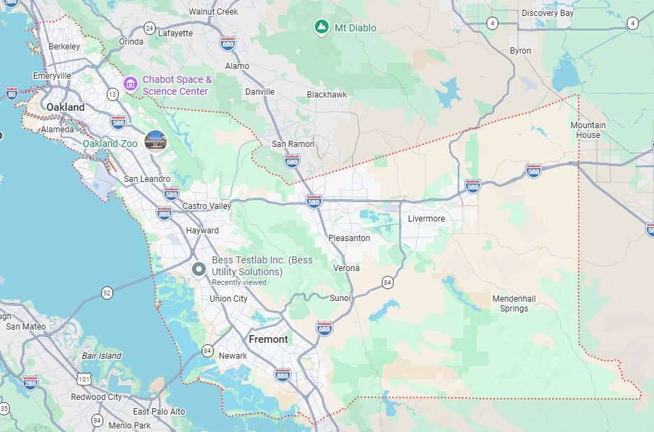
Hayward, CA
(408) 988-0101
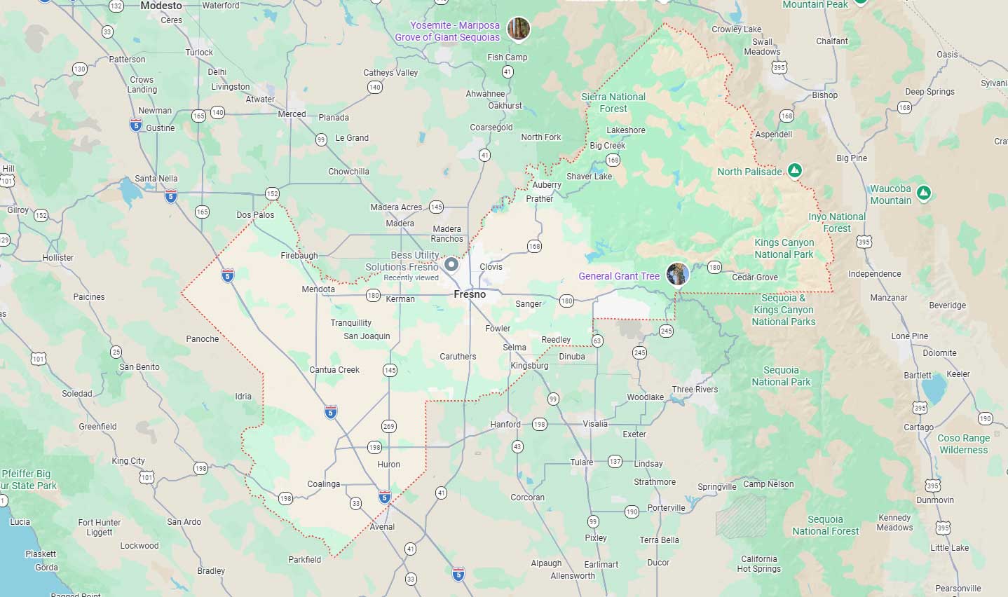
Fresno, CA
(559) 272-1375
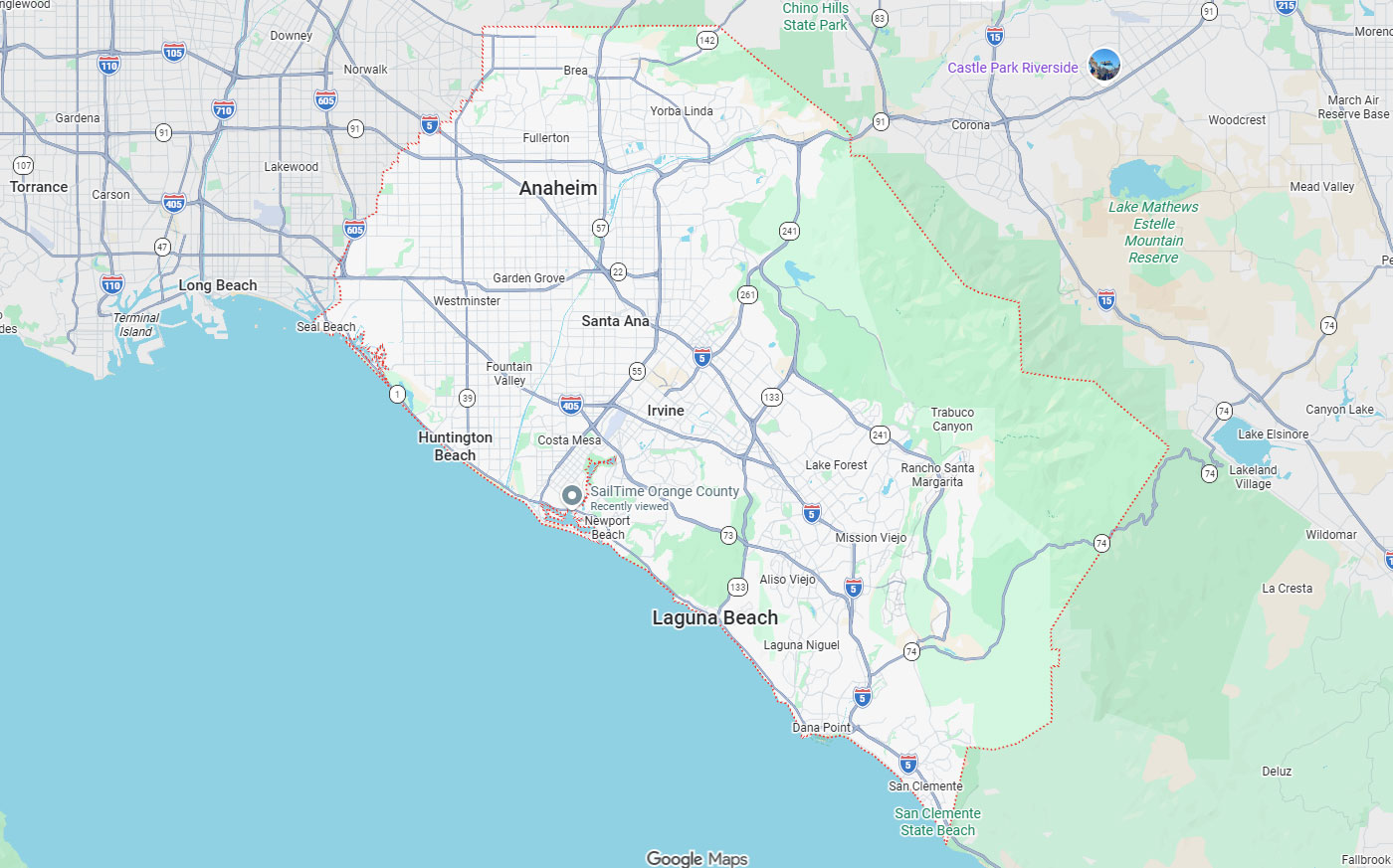
Orange, CA
(909) 510-5535
Sacramento, CA
(510) 461-1792
Phoenix, AZ
(602) 633-7200

GPR vs. EM Locating: Which Technology Is Right For Your Project?

February 3, 2026 / Written by: Bess Utility Solutions

February 3, 2026
Written by: Bess Utility Solutions

Key Takeaways

  • Material Detection Determines Technology Choice: EM locating works only for metallic utilities (or non-metallic with tracer wire), while GPR detects both metallic and non-metallic materials, including PVC pipes, concrete, and fiber optics, making GPR essential for comprehensive subsurface mapping in mixed-utility environments.
  • Multi-Technology Approach Delivers Proven ROI: Combined EM and GPR deployment saves $4.62 to $22.21 for every $1 invested, reduces project delays by 9.08%, and cuts construction costs by 29.46%, with case studies documenting 50% reduction in utility strikes when both technologies are employed.
  • Site Conditions Fundamentally Impact Technology Effectiveness: Soil moisture and conductivity create critical performance variations, GPR penetration drops from 30 feet to mere inches in wet clay, while EM maintains effectiveness; conversely, dry sand/gravel favors GPR's maximum 50-meter depth capability.
  • ASCE 38-22 Quality Level B Requires Surface Geophysics: Achieving the 0.2 ft (60 mm) horizontal accuracy standard for QL-B necessitates surface geophysical methods, typically both EM and GPR, making combined deployment standard practice for federally funded projects and critical infrastructure work.
  • Cost-Effective Strategies Exist for Budget-Conscious Projects: Strategic approaches include EM rental ($300/week) for short-term metallic utility work, phased investigations starting with lower-cost EM sweeps supplemented by targeted GPR, and using QL-D/QL-C data for preliminary work while reserving expensive QL-A vacuum excavation for critical conflict points only.

Utility strikes cost the construction industry billions annually while creating significant safety hazards and project delays. The Common Ground Alliance reports utility damage incidents increased from an index of 94.0 in 2023 to 96.7 in 2024, with 94% of damages attributed to incomplete or inaccurate subsurface information. Selecting the right utility detection method, Ground‑penetrating radar (GPR), Electromagnetic (EM) locating, or a combined approach, directly impacts project safety, schedule, and budget.

This comprehensive guide examines the technical capabilities, cost structures, and optimal applications for both GPR and EM locating technologies within the framework of ASCE 38-22 Subsurface Utility Engineering standards. Understanding when to deploy each method, and when combining both becomes necessary, enables informed decisions that minimize utility strike risk while controlling investigation costs.

Choosing the right technology for underground utility detection directly impacts project costs, safety, and schedule. Ground-penetrating radar (GPR) and EM locating represent the two primary methods for identifying buried utilities, each with distinct capabilities, limitations, and cost structures. This utility detection comparison helps determine project suitability for each technology, or when to combine both, which is essential for achieving ASCE 38-22 Quality Level B compliance and minimizing utility strike risk.

What Is Ground Penetrating Radar (GPR)?

Ground Penetrating Radar is a non-destructive geophysical method that detects both metallic and non-metallic subsurface features by transmitting electromagnetic waves into the ground and recording reflections from material boundaries.

How Ground Penetrating Radar Works

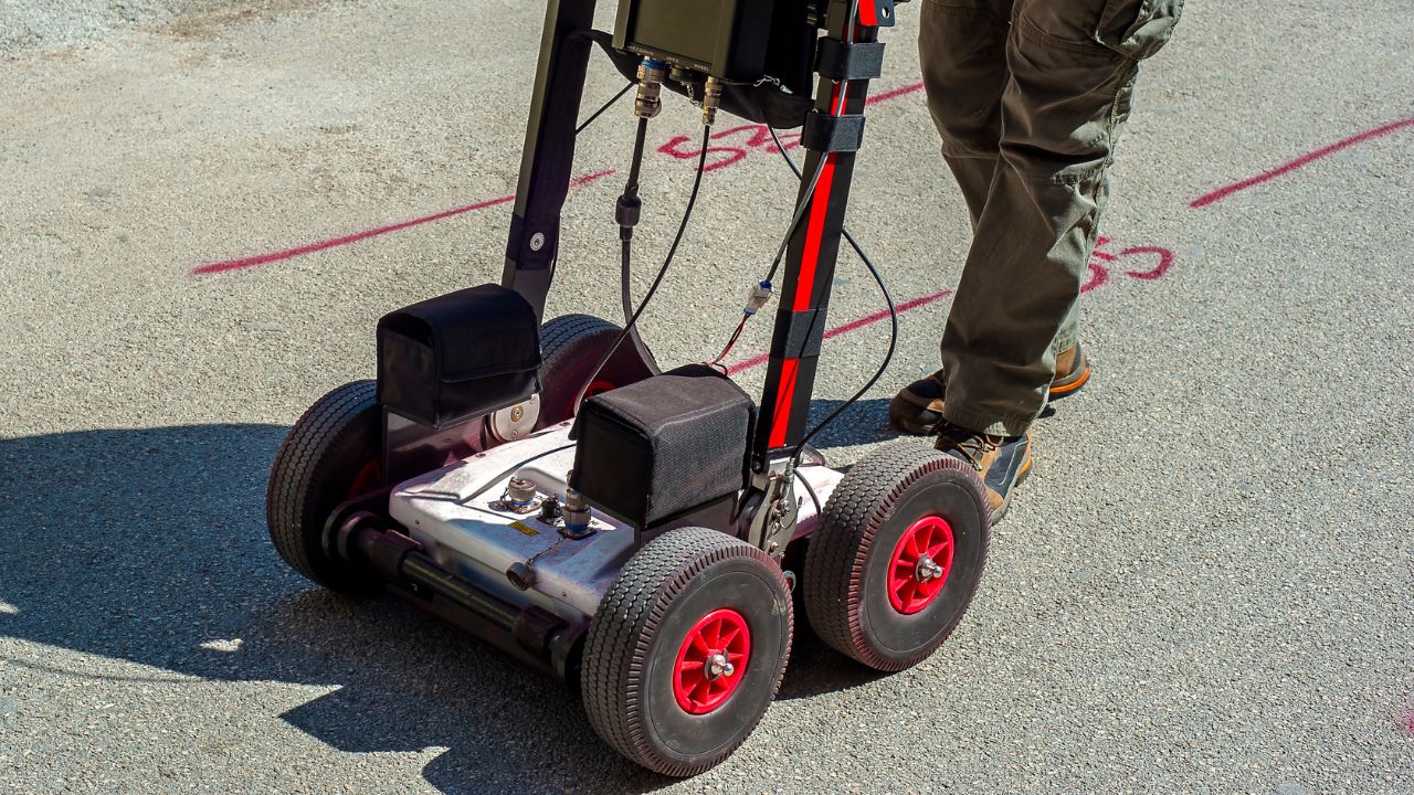
GPR systems transmit radio waves (25-1,500 MHz) into the subsurface and measure the two-way travel time and amplitude of reflected signals. When electromagnetic waves encounter boundaries between materials with different dielectric permittivity values, reflections occur and are recorded. The system processes these reflections into a radargram, a cross-sectional image showing subsurface structures and their depths.

The technology's fundamental advantage stems from its reliance on dielectric contrast rather than electrical conductivity. This allows GPR to detect any material interface, including non-metallic utilities invisible to electromagnetic locators. Frequency selection determines the trade-off between resolution and depth: higher frequencies (900 MHz-1.5 GHz) provide detailed shallow imaging, while lower frequencies (25-200 MHz) penetrate deeper with reduced resolution.

Advantages Of GPR

  • Detects non-conductive materials: Can locate PVC pipes, concrete structures, fiber optic cables, and voids
  • Superior horizontal accuracy: Achieves ±2-4 inches in ideal conditions, compared to ±6 inches for EM locating
  • High accuracy rate: Services using GPR report 99.8%+ accuracy in utility locating
  • Depth accuracy: Typically within ±10% of actual depth, improvable to within a few percent with calibration
  • Versatile depth capability: 15-30 feet in favorable soil conditions using 100-200 MHz antennas; up to 50 meters in dry sand/gravel and 100 meters in ice under ideal conditions
  • Comprehensive subsurface imaging: Provides visual radargrams showing both metallic and non-metallic objects with depth information

Disadvantages of GPR

  • High equipment cost: Professional utility locating services range from $10,000 to over $100,000
  • Steep learning curve: Requires minimum 8 hours formal training and 60 hours of practice for proficiency
  • Ongoing operational costs: Annual calibration costs approximately $2,400; may include software licensing fees
  • Limited penetration in conductive soils: High-conductivity materials (wet clay, silt, saline soils) can reduce penetration depth to mere inches (6-12 inches) due to rapid signal absorption
  • Environmental sensitivity: Water's dielectric constant is approximately 27 times higher than common soil minerals, causing pronounced signal attenuation in high-moisture environments
  • Surface condition requirements: Rough terrain, dense vegetation, or standing water prevent necessary close antenna-ground contact
  • Slower data collection: Survey speed is generally slower than simple EM tracing

What Is Electromagnetic (EM) Locating?

Electromagnetic locating is the primary method for detecting and tracing metallic utilities by inducing or receiving electromagnetic fields from buried conductors.

How Electromagnetic Locating Works

EM systems detect magnetic fields generated by alternating current flowing through metallic conductors. In active mode, a transmitter applies a specific AC signal to the target utility through direct connection (most effective), inductive clamp, or broadcast induction. The receiver then traces this electromagnetic field to determine horizontal position and estimate depth.

Passive mode detects naturally occurring fields from energized power lines (50/60 Hz) or VLF radio signals coupled onto metallic utilities. Common active frequencies include 512 Hz for long-distance tracing with minimal signal loss, 8 kHz for general-purpose locating, and 83 kHz for induction in poor conductivity conditions. 

Depth estimation relies on signal strength measurements using peak mode (maximum signal directly over utility) or null mode (minimum signal over utility), achieving better than 10% accuracy when separation distance exceeds twice the depth.

Advantages Of EM Locating

  • Low equipment cost: Professional-grade devices range from $800 to $10,000
  • Minimal training requirements: Short and simple training with gentle learning curve; operators become proficient with minimal instruction
  • Cost-effective rental option: Approximately $300 per week
  • Fast and efficient: Quick for tracing conductive utilities like metal pipes and cables
  • Low operational costs: Primarily battery replacement and minimal maintenance
  • Multiple frequency options: 512 Hz for long-distance tracing, 8 kHz for versatile active locating, 33 kHz and 83 kHz for various applications
  • Effective for specific utilities: Ideal for metallic pipes (iron, steel, copper), copper telecom lines, and energized electrical cables

Disadvantages Of EM Locating

  • Limited to conductive materials: Cannot detect non-conductive utilities (PVC, concrete, fiber optics) without metallic tracer wire
  • Lower horizontal accuracy: Typically ±6 inches compared to ±2-4 inches for GPR
  • Signal distortion issues: 90° bends can introduce positional error up to 33% of utility depth; parallel lines carrying similar signals require separation of nearly 10 times the depth for accuracy better than 10%
  • Environmental interference: Performance affected by dry or rocky soils; electromagnetic interference from power lines, metallic fences, or active electrical equipment
  • False negatives: Occur when utilities are non-conductive or when the signal is severely distorted or attenuated
  • Depth limitations: Typically 0-15 feet for active location, less than GPR's potential 30-foot range

How Do GPR and EM Locating Technologies Differ?

The fundamental distinction lies in detection principles: GPR uses dielectric contrast to image all subsurface features, while EM locates traces of electromagnetic fields from conductive utilities only. This creates complementary strengths that drive industry-standard multi-technology approaches for comprehensive utility mapping.

Performance Comparison

FactorGPREM Locating
Depth of Penetration15-30 feet (typical soil, 100-200 MHz); up to 50m in dry sand/gravel; 100m in ice0-15 feet (active location)
Material DetectionMetallic and non-metallic (PVC, concrete, voids, fiber optics)Metallic/conductive materials only (or non-metallic with tracer wire)
Horizontal Accuracy±2-4 inches (ideal conditions)±6 inches
Depth Accuracy±10% (typically); improvable to few percent with calibrationBetter than 10% when separation is twice depth or greater
ResolutionHigh frequencies (900 MHz-1.5 GHz) = high resolution, shallow depth; Low frequencies (25-200 MHz) = lower resolution, deeper penetrationConsistent across operating range
Survey SpeedSlower data collectionFast and efficient for conductive utilities
Detection PrincipleReflection from dielectric permittivity contrastsElectromagnetic field from AC current in conductors

Cost Differences

Cost CategoryGPREM Locating
Initial Equipment Cost$10,000 to over $100,000 for professional systems$800 to $10,000 for professional-grade units
Rental CostN/A (typically hired as service)~$300 per week
Training CostMinimum 8 hours formal training + 60 hours practice requiredMinimal instruction; short and simple training
Annual Calibration~$2,400 for standard 6-point calibrationNot typically required
Software LicensingMay include fees for advanced data processingNot applicable
Service Daily Rate$800 to $5,000 per day depending on complexityLower operational costs primarily for batteries

Accuracy Comparison

Application TypeGPR AccuracyEM Locating Accuracy
Non-metallic Utility Mapping±2-4 inches horizontal (ideal); ±10% depthCannot detect without tracer wire
Metallic Utility Mapping±2-4 inches horizontal (ideal); ±10% depth±6 inches horizontal; better than 10% depth (when separation ≥2× depth)
Concrete ScanningHigh resolution with 900 MHz-1.5 GHz antennasNot applicable
Void DetectionEffective for subsurface anomalies and voidsNot applicable
Energized Line Detection±2-4 inches horizontal; ±10% depth±6 inches horizontal; effective with passive detection (50/60 Hz)

Depth Of Detection

Soil/Material TypeGPR Maximum Detection DepthEM Locating Maximum Detection Depth
Dry Sand/GravelUp to 50 meters (164 feet)0-15 feet (active location)
IceUp to 100 meters (328 feet)Not typically applicable
Typical Soil (low-frequency antenna)15-30 feet (100-200 MHz antenna)0-15 feet (active location)
Wet Clay/Silt6-12 inches (severely limited)0-15 feet (reduced in dry/rocky soils)
Saline/High-Conductivity SoilCentimeter scale (severely limited)0-15 feet (signal may be reduced)
Rocky TerrainVariable; depends on conductivityReduced signal transmission

When Should You Use GPR vs. EM Locating For Your Project?

Technology selection depends on utility type, accuracy requirements, budget constraints, and project complexity. Neither method is universally superior; optimal results often require understanding when each technology excels and when combining both approaches becomes necessary for comprehensive subsurface mapping. For insights on regional applications, see our detailed analysis of GPR vs. electromagnetic locating for Arizona projects.

When To Choose GPR

  • Non-metallic utility detection required: For locating PVC water/sewer pipes, concrete conduits, or fiber-optic cables
  • High accuracy needed: When projects demand ±2-4 inch horizontal accuracy
  • Comprehensive subsurface mapping: Need visual radargrams showing complete subsurface profile
  • Void and concrete scanning: Detecting subsurface anomalies, rebar, post-tension cables, or assessing concrete cover
  • Low-conductivity soils: Working in dry sand, gravel, or other favorable soil conditions
  • ASCE 38-22 Quality Level B compliance: Surface geophysics requirement for documenting utility existence and horizontal position (0.2 ft/60 mm tolerance)
  • Mixed utility infrastructure: Areas containing both metallic and non-metallic utilities
  • High electromagnetic interference environments: Where EM signals would be unreliable

When To Choose EM Locating

  • Metallic utility tracing: For iron/steel pipes, copper telecom lines, or energized electrical cables
  • Budget constraints: Initial investment of $800-$10,000 vs. $10,000-$100,000+ for GPR
  • Quick deployment needed: Minimal training requirements and fast setup time
  • Long-distance utility tracing: Using 512 Hz frequency for extended pipeline mapping
  • Simple utility corridors: Known metallic infrastructure with low congestion
  • Tracer wire applications: Non-metallic pipes equipped with metallic tracer wire
  • Passive detection scenarios: Locating energized power lines using 50/60 Hz signals
  • Cost-sensitive projects: Rental option at ~$300/week available
  • Operator experience limited: Short learning curve suitable for quick training

Using GPR And EM Locating Together

Multi-technology approaches have become industry standard for high-stakes projects, combining GPR's ability to detect all materials with EM's efficiency for metallic utility tracing. This combination directly addresses the 94% of utility damage incidents attributed to incomplete or inaccurate subsurface information.

The cost-benefit analysis strongly supports combined deployment: studies show $4.62 to $22.21 saved for every $1 invested in comprehensive SUE, with 9.08% reduction in project delays and 29.46% reduction in construction and design costs. Real-world validation includes a Chicago municipal case study documenting 50% reduction in utility strikes over five years using integrated EM and GPR data. 

For ASCE 38-22 Quality Level B compliance, requiring 0.2 ft (60 mm) horizontal accuracy, the multi-technology approach is standard practice, particularly in complex corridors where a single trench may contain metallic gas lines detectable by EM alongside non-metallic fiber-optic conduits requiring GPR.

How Do Site Conditions Impact Your Technology Choice?

Environmental factors fundamentally determine detection effectiveness for both technologies. Soil composition, moisture content, and electromagnetic environment can shift viable technology selection from one method to another, or necessitate combined deployment for reliable results.

Site Factors For GPR

  • Soil moisture content: Water's dielectric constant (27× higher than soil minerals) causes pronounced signal attenuation in wet conditions
  • Soil conductivity: High-conductivity materials (saturated clays, saline water) limit penetration to centimeter scale
  • Antenna frequency selection: High frequencies (900 MHz-1.5 GHz) for shallow, high-resolution work; low frequencies (25-200 MHz) for deeper penetration up to 30 feet
  • Surface conditions: Rough terrain, dense vegetation, or standing water prevent necessary antenna-ground contact
  • Target depth and size: Deeper, smaller targets harder to resolve; optimal for targets within frequency-appropriate depth range
  • Material dielectric constant: Accurate determination needed for precise depth calculation
  • Intrinsic attenuation: Primary limiting factor controlled by electrical conductivity; severely limits depth in high-conductivity environments

Site Factors For EM Locating

  • Soil type: Dry or rocky soils reduce signal transmission effectiveness
  • Electromagnetic interference: Performance affected by nearby power lines, metallic fences, or active electrical equipment
  • Utility configuration: 90° bends introduce positional error up to 33% of depth; parallel lines require separation of nearly 10× depth for <10% accuracy
  • Utility congestion: Signal jumping or masking between closely spaced, parallel metallic lines in congested corridors
  • Tracer wire integrity: Broken or absent tracer wires prevent non-metallic utility detection
  • Soil conductivity: Better signal propagation in conductive soils compared to dry/rocky conditions
  • Frequency selection: 512 Hz for long-distance/minimal bleed-off; 83 kHz for poor ground conductivity (though signal dissipates quickly)

Soil Type, Moisture, and Interference

Seasonal and environmental variations create dynamic detection challenges requiring adaptive technology selection. Wet clay or silt reduces GPR penetration from several feet to 6-12 inches, making EM the viable choice for metallic utilities in these conditions. Conversely, dry sand or gravel enables GPR's maximum penetration up to 50 meters while EM maintains its standard 0-15 foot range.

High electromagnetic noise environments, near power lines, industrial facilities, or dense metallic infrastructure, degrade EM locating accuracy while leaving GPR unaffected. Rocky terrain challenges both technologies variably. Saline or high-conductivity soils render GPR virtually ineffective (centimeter-scale penetration) while EM maintains functionality. 

The Common Ground Alliance Index increased from 94.0 (2023) to 96.7 (2024) reflects rising utility damages, underscoring the consequences of inadequate technology selection for site-specific conditions.

What Are The Real-World Applications Of GPR And EM Locating?

Both technologies serve distinct and complementary roles across infrastructure sectors, from transportation and municipal utilities to environmental assessment and archaeological investigation. Understanding application-specific requirements guides appropriate technology selection.

Applications of GPR in Utility Mapping and Infrastructure Inspection

  • Non-metallic utility detection: PVC water/sewer pipes, fiber-optic cables, concrete conduits
  • Concrete structure scanning: Locating rebar, post-tension cables, conduits; assessing concrete cover and thickness
  • Void detection and mapping: Subsurface anomalies, karst features, burrows, and cavity identification
  • Blind search applications: Scanning areas for any anomaly without prior knowledge of targets in environmental, engineering, and archaeological surveys
  • Mixed-material utility corridors: Areas with both metallic and non-metallic infrastructure requiring comprehensive mapping
  • ASCE 38-22 QL-B investigations: Surface geophysical method for determining utility existence and horizontal position (0.2 ft tolerance)

Applications of EM Locating In Utility Detection and Mapping

  • Metallic gas line tracing: Efficient for steel and iron pipelines using active location modes
  • Electrical cable location: Copper telecom lines and energized power cables using both active and passive (50/60 Hz) detection
  • Metallic water/sewer pipes: Direct tracing of iron and steel distribution systems
  • Tracer wire applications: Non-metallic utilities equipped with copper tracer wire for detection
  • Sonde insertion: 512 Hz or 33 kHz sondes for tracing non-conductive pipes (sewer lines) from inside
  • Long-distance pipeline mapping: 512 Hz frequency minimizes signal bleed-off for extended utility tracing
  • Quick utility sweeps: Fast initial assessment of metallic utility congestion in project areas

Other Applications for GPR and EM Locating

  • GPR - Archaeological surveys: Non-invasive subsurface investigation of historical sites
  • GPR - Environmental assessment: Soil contamination mapping, groundwater table identification
  • GPR - Pavement analysis: Assessing pavement thickness, detecting delamination
  • GPR - 3D utility visualization: Integration with GNSS for complete spatial modeling (GTI Energy case study)
  • EM - Pipeline integrity monitoring: Detecting faults in electrical systems and pipeline coating defects
  • EM - Inductive clamp applications: Non-invasive signal application to accessible utilities
  • EM - Direct connection method: Most effective signal application for precise metallic utility tracing
  • Combined - Federal highway projects: FHWA-encouraged SUE for Federal-aid projects with eligible reimbursement costs

Which Technology Is Right For Your Project?

Choosing the right utility-detection technology comes down to aligning performance, site conditions, budget, schedule, and ASCE 38-22 compliance needs, because no single method fits every scenario. EM is best for quickly tracing metallic utilities with minimal training and lower cost, while GPR supports broader subsurface mapping (including non-metallics) with higher accuracy and greater depth in favorable soils but requires more investment and operator expertise. 

The most reliable and cost-effective approach for complex projects is often a phased, multi-technology strategy: start with lower-cost records and surface review (QL-D/QL-C), run EM sweeps for conductive lines, and add targeted GPR where non-metallic detection or comprehensive mapping is required, escalating to QL-A vacuum excavation in critical conflict zones. Short-term work can leverage EM rentals or GPR service providers to avoid capital and training costs, and design choices like installing tracer wire can reduce future locating expenses; always confirm state/DOT and PE requirements before mobilizing.

Ready to implement the right utility detection strategy for your project? Contact BESS Utility Solutions for expert guidance on technology selection and professional utility locating services tailored to your specific requirements.

Contact Us

We prioritize clear communication and reliable solutions to meet your specific requirements. Get in touch with us today, and let's work together to ensure the safety and efficiency of your projects.

© 2026 Bess Utility Solutions. All Rights Reserved.